Typical Components - Work Supports
| Once a part has been positioned on the fixture, the next step in workholding is to provide support where needed to prevent part deflection or vibration during machining. It’s important not to confuse work supports with the support points and planes inherent in the positioning step! As explained in the previous chapter, rigid support points or surfaces additional to those used in the 3-2-1 locating process must not be introduced. After a part has been positioned, the work support advances to contact the part with slight pressure, then locks in place. This can be accomplished in these ways: |
1. Spring advance – The weight of the part compresses a spring behind the plunger. When the part is in place, the plunger is locked. 2. Air advance – Air pressure is used to advance the plunger to contact the positioned part, and then the plunger is locked. 3. Hydraulic advance – hydraulic fluid is used to advance the plunger to contact the positioned part, and then the plunger is locked. For each advanced method, locking is accomplished by applying hydraulic pressure to a sleeve that compresses to lock the plunger in place. |
 |
 |
||
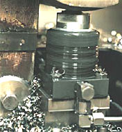
Typical Components - Swing Cylinders |
||
After a part has been positioned and supported, it must be clamped where needed to complete the workholding process. The swing cylinder is  without doubt the most widely used clamping device. As the plunger travels from the extended position to the retracted position, the clamp arm rotates, usually 90°. without doubt the most widely used clamping device. As the plunger travels from the extended position to the retracted position, the clamp arm rotates, usually 90°.The 90 degree rotation of the clamp arm eliminates interference when the part is mounted to the fixture or removed. Stroke and capacity Stroke and capacity are parameters of concern, just as with positioning cylinders. Choice of cylinder stroke length is primarily affected by the geometry of the part to be clamped. Capacity, the clamping force, is selected in accordance with the machine cutting forces that must be resisted. |
Mounting styles Mounting styles provide flexibility to meet requirements of part geometry, fixture space, and accessibility for loading and unloading. Oil feed to flanged and threaded models can be via external plumbing or a fixture manifold. Cartridge models recess into a fixture manifold for an extremely compact setup. Single- and Double-acting As with the positioning cylinders, most cylinders are available in either single- or double-acting form. Arm Length Arm length is a parameter that allows design flexibility. However, the longer the arm, the higher the side load on the cylinder. Consequently, the longer the arm, the less clamping force available. Clamp arms are available in a variety of lengths, or you can machine your own configurations. Product literature provides information on allowable pressure and clamping force as a function of arm length. |
 |
|
|
||||
TM and © Enerpac 2002
All rights reserved. Reproduction of any materials without Enerpac’s permission is strictly prohibited.